Builder Visits - 2nd Visit to Mikey
On a Saturday in late August, I traveled once again to Mikey’s shop in Baltimore to pick up my completed amp. I don’t have to tell you I was pretty excited on the drive from my house. This was going to be the first time I’d get to see the completed main board installed in the chassis and hooked up to the rest of the components.
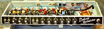
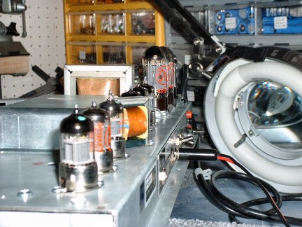
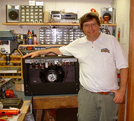
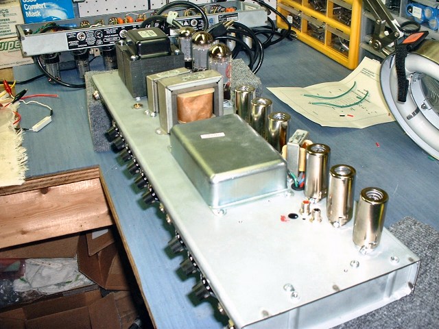
Completed chassis, just waiting for me to try it out
I arrived at 1:30 and spotted the friendly cat peering out the window at me as I walked up to the front door. Mikey thought it would be enjoyable to sit out back and talk about the project we’d both been working on for seven weeks. Of course, he’s been doing the building and I’ve been doing the writing. You may be surprised to know I’ve put more than 150 hours into crafting this tale and creating this website. It’s a labor of love though, since I’m the one benefiting the most by having to explain what I’m learning.
We grabbed a couple of soft drinks and as Mikey was getting the ice and glasses, I was able to make peace with the other cat that was recalcitrant on my last visit. The cat’s name is Simba and at first, he scampered away when I came too close but I was able to coo and woo him into accepting my ministrations of petting, although he didn’t seem to think too highly of the whole process.
Mikey and I settled in deck chairs on the patio and spoke of all the work leading up to this point in time. He said when he completed the chassis last night, he fired it up to make sure everything was performing properly, using his tubes in my new amp. He said he was going to have me install and bias my tubes as an inaugural gesture.
After our conversation, we went to the shop to look at my amp.
While I had learned a lot from the pictures and emails from Mikey during the build, and from researching concepts I wasn’t familiar with, I still had some questions about tube amp theory. This was a great time to get some questions answered and Mikey obliged. He gave me a guided tour of the interior of the amp using a wooden chopstick (to prevent shocks). While most of the amp’s sections are already documented, here are some of the new things I learned.
Perhaps you’ll recall in the “Bias Test Points” section, I made mention of Mikey measuring the plate voltages of the 6V6 tubes in order to calculate the right bias setting. He hooked up a multimeter, which showed the left tube at 401.8 volts and the right tube at 402.5 volts. If you look back at the formula, you’ll see the 25mv setting at the bias test points will be just fine with these plate voltages. However, these plate voltages will likely change when the new Mercury Magnetics power transformer is installed next month so this will be checked again at that time.
Speaking of power transformers, talking with Paul, Sergio and Mikey the other day about the new power transformer sparked a new level of interest on my part about this important aspect of tube amps. It’s funny, I’ve read the text books on power transformers and looked at the diagrams but it wasn’t until today that I feel I finally have a grasp on how it does what it does and why it is so critical. Maybe as consumers we are used to plugging into an AC outlet in the wall and getting power that we may tend to think of as not-too-complicated and very straightforward. I’m sure to an engineer, my next statement seems like a “duh” moment, but the power transformer does its magic by stepping voltages up or down depending on what is needed.
I’ve known from the textbooks that transformers are made from coils of wire wrapped around a magnetic core and when you place a coil of wire next to another one, a signal in one coil is “induced” into the neighboring coil(s). There are wires going into the first coil (called the primary) and wires coming out of the second coil (called the secondary). If the number of turns of wire in the primary and secondary are the same, the voltage will be the same in both. If there are twice as many turns in the secondary, the voltage will be double what it is in the primary.
As an example, if you take 120 volts AC coming from the power switch (which is connected by the AC power cable to the wall outlet), the secondary will have 240 volts of AC on it. Voltages can be stepped down in the same way by putting fewer turns of wire on the secondary coil. And guess what, there are multiple secondaries in the same power transformer.
What Mikey helped me with today was actually looking at where the connections to and from the power transformer are made in the amp. I think this really helped me visualize and understand what is happening in the amp in a practical sense, not just as theory. I got a lot of my questions answered, although as I am writing this, I needed to pick up the phone for some additional help from Mikey. We looked at photos of the chassis and he referred me to an excellent diagram on Doug Hoffman’s website:
Hoffman AB763 board layout (click on picture for a larger view)
You’ll notice this layout is different than the Fender Deluxe Reverb AB763 layout shown previously in the “Rebuild Discussions” section. This is because Doug did a redesign of the layout. It is this layout Mikey has used as the foundation for my amp, although he certainly has added a number of enhancements and mods. Since this diagram is very close to my amp, Mikey used it to help explain more about the power section of my amp including the power transformer, rectifier, standby switch, filter caps, choke and dropping resistors.
Another diagram I found helpful is this current flow diagram from Doug’s site. Although it is for a Plexi circuit instead of the AB763, it has arrows showing how the currents are flowing through the various sections of the amp.
Hoffman Current Flow Diagram (click on picture for a larger view)
In trying to learn and write about these sections of the amp, I’ve found myself going back to Doug’s site a number of times today. It is chock full of information and diagrams to help people like me understand what our amps are doing. For convenience, here’s a link to the Hoffman Amplification Library of information.
With my new-found knowledge, I can tell you the power transformer takes the 120 AC volts from the wall outlet and has secondaries to step it down to 5 volts AC to heat the cathode of the rectifier tube and to 6.3 volts AC to heat the pilot light and the cathodes of the rest of the tubes Hoffman Current Flow Diagram (click on picture for an external link)
As you’ve read, a lot of the amp runs on DC power (just like the batteries in your flashlight), and this has to be created by the power transformer and the rectifier tube. There’s a secondary from the power transformer to carry the AC current to the 5AR4 rectifier tube, which converts AC into pulsating DC. This high DC voltage (more than 400 volts – sometimes called B+) goes to the standby switch and then to big electrolytic filter caps that smooth out the rippling/pulsating DC power into smooth DC power. Take another look at the filter cap board.
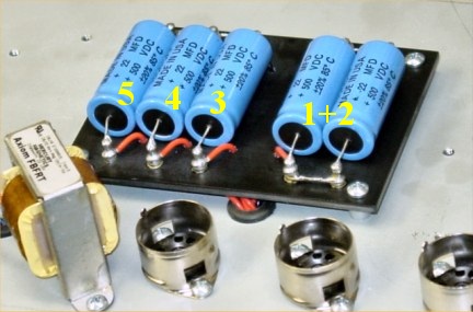
Filter caps 1 & 2 in parallel. Filter caps 3, 4, 5 for other amp sections.
The pulsating DC coming off of the rectifier tube goes into the parallel filter caps (1 & 2) to smooth and filter the pulsating DC. The output transformer is fed off of these two parallel caps. The now-smooth DC voltage flows from these caps to the choke, which as you’ll recall is an inductor that has the property of opposing changes in current, so, the choke smoothes the current. Of interest, even when you turn off the amp, the current in the inductor doesn't stop immediately. It takes longer for the current to stop in the inductor because of the nature of the inductor and its opposition to changes in current.
The current continues on the power rail to filter cap 3 on the way to the 1K/5W screen resistors.
Current simultaneously passes along the power rail through a dropping resistor (to lower the voltage) and then through filter cap 4 on the way to the phase inverter. It also passes further along the power rail to another dropping resistor and filter cap 5 to provide smooth power at lower voltage to preamp sections. Here’s a part (edited by me) of Doug’s AB763 layout showing the placement of the power transformer, rectifier, standby switch, filter caps, choke and dropping resistors. You can match the layout up with the actual photo of the filter cap board.
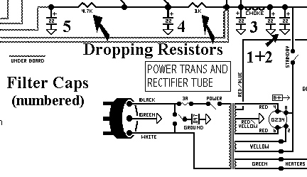
Blow-up of the Hoffman AB763 layout with numbered filter caps and dropping resistors
Well, I think this is about as far as I can take my explanation of the power supply section of the amp. It sure helps having Mikey to talk to and a great site like Doug’s to visit for the diagrams and further explanations. I really learned a lot in the last two days. I’ve just scratched the surface, but if you want more info, it’s out there.
After Mikey and I got through discussing the power section, we needed a break so we commandeered our haunt on the back patio, drinks in hand. About this time, one of Mikey’s sons stopped by and I got to meet him briefly. We sipped our Cokes and thought aloud what the reactions to this website might be. Neither he nor I am aware of a customer having gone to this much detail about a builder’s work.
We’ve seen websites of people building David Allen’s kits, pictures from the AX84 projects, and of course photos from all of the regular and boutique amp builders’ sites, but Mikey and I seem to have struck on a symbiotic relationship that will show folks what he’s up to, while simultaneously helping me get some education. Believe me, it’s been a LOT of extra work on Mikey’s part to feed me photos and information during this rebuild but I know he’s getting a kick out of having the whole process documented.
The rebuilt amp is fitted with tubes and is ready to fire up
By this time, I’d been at Mikey’s for about 3.5 hours and it was time to return to the shop for the christening of my amp. Mikey took all of his tubes out of my amp and we lined up the tubes I’d had in my DRRI before the rebuild, except for the power tubes, which are the new JJ 6V6’s I’d just received from Lord Valve. I’ve been curious to try them out. I carefully inserted all of the tubes into the amp. The moment was at hand.
Once all the tubes were installed and the speaker plugged in, I flipped on the power switch and let it warm up. I hooked up the multimeter to the bias test points and flipped on the standby switch. It took just a minute to bias the 6V6 power tubes to the 25mv setting and I was ready to play.
I plugged in my favorite Hamer Artist Custom and beautiful tones erupted from the Normal channel. We switched to the Vibrato channel and it was excellent too.
I was curious about the Triode/Pentode switch so I put the amp on standby (something you should always do when using this switch) and put it in Triode mode. The amp was a bit darker and it growled at a lower volume. Pretty neat. And my-oh-my, Mikey certainly had come through with enough brightness, as I’d hoped. Even in Triode mode with a neck P-90 pickup, there was plenty of top-end to satisfy me with the amp’s treble setting on about 7.
Naturally, the amp sounds different when it is out of the chassis so I shut the amp down and Mikey put the chassis into my cabinet and hooked up the reverb pan to the new RCA jacks at the bottom of the chassis. Just before he attached the back plate, I snapped a photo.
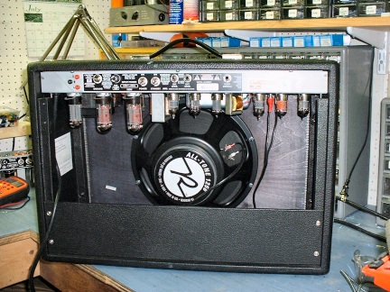
The back of my amp without the back plate. Note the Reverend All-Tone speaker
After the amp was buttoned up, it was time to give it a workout. I was astonished at how smooth, snappy and swirly the Vibrato channel sounded. It made my pulse quicken. My first thought was this is the great tone I’ve heard in the blues clubs of Chicago. My company’s headquarters are in Chicago (I’m a printer by trade) and when I get out there, I spend my evenings in the blues clubs. Depending on how I dialed in the amp and my guitar, I could go from a swampy, smoky sound to the brilliant tones of Albert Collins. I like a nice, crisp attack to the notes and the Vibrato channel has got it.
Then I turned on the reverb with the Mercury transformer and the new audio pot and once again, I was just in love right away with the sound; always a good sign. I switched over to the Normal channel with the more Marshallesque tone and let it rip. I was crunching and sustaining to beat the band. Both the P-90 and Seth-Lover humbucker sounded great. The tremolo is hypnotic. Much better than the on/off circuit in the stock DRRI. I’ll use this to add a subtle swooshing sound for some songs.
I’m not going to go into a lot of my tonal impressions in this section since I will continue to document my impressions in the “Playing The Amp” section as time goes by. Let me just say my first impressions of the amp are that IT ABSOULUTELY SOUNDS FANTASTIC!!!!!
I relinquished control to Mikey who took a few sonic excursions. It was nice being able to focus on the sounds of the amp and not my playing. I got goose bumps. I got chills. My endorphins were souping me up. I was excited, satisfied and really, really pleased. I could see Mikey felt the same. Hip, Hip, Hooray!
While Mikey continued to play, I went over to my kit bag to make out a check for the amp. I don’t recall it ever being so easy to part with a chunk of dough for gear. I kind of felt sorry for Mikey because I was going to be the one to take it home and enjoy it. LOL. Of course, he has his own rebuild so he won’t really be roughing it.
Mikey stopped playing and I handed him the check and thanked him profusely. Then he surprised me. From the back of the workbench he pulled a small, gift-wrapped package and handed it to me. I tore off the wrapper to find a Amperex Bugle Boy 12AX7 to use in my amp. What a thoughtful thing to do.
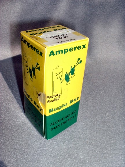
Amperex Bugle Boy 12AX7 preamp tube
If you look closely, you can see it still has the “Factory Sealed” tape holding the box closed. This photo has generated an interesting discussion on The Gear Page regarding the origin of this tube and box since it says “Made in USA” but Amperex tubes were manufactured in Holland. I’m going to find just the right spot for it in my amp.
About this time, Mikey’s wife came home from the pool. I packed up my stuff and then had a chance to talk with her for a little bit. I told her how pleased I was with the amp. We chatted some more and then Mikey and I sat out on the patio to unwind. It took awhile. We were both jazzed and amazed. The amp met our highest expectations. We marveled at the journey we’ve both been on and we’re both looking forward to having a little more free time for a week or two :>)
I’ve got a gig on the Saturday of Labor Day weekend so that’ll be the first public appearance of the amp and I'll make sure to give a sonic report from the experience. I’ve got that following week off and I’m going to the shore for some relaxation. I expect the first time people will see this article is over Labor Day weekend. I should have everything on the website ready to go by then, so if you are reading this, mission accomplished. LOL.
My amp and me
Mikey and I ended up talking for a couple of hours and as the sunlight started to fade, I packed up my new amp and started the drive back to Lancaster County, satisfied and full of expectations. When I got home, I plugged in and played for a solid hour. You can read about it in the next section.
I’ll close by mentioning the rebuild isn’t done yet. Remember, Mercury Magnetics is making a new power transformer for Mikey to put in my amp. A week or two after I get back from the shore, I’ll go back to his shop to have it installed. Heck, by the time the new power transformer breaks in, it’ll be well into October before I’ll be able to complete a thorough write-up of what the amp sounds like. If you want to read the latest developments, check back in from time-to-time for news of additional tweaking, tone reports and clips. Now, I think I’ll go play some amp, er, I mean guitar :>)
Builder Visits - 3rd visit to Mikey
In October, I returned to Mikey's shop for the installation of the Mercury Magnetics Power Transformer and some final tweaks to the amp based on six weeks of playing it at home and with the band. Please take a look at the Mercury Magnetics page. I thought it appropriate to cover the PT installation there.
It was good to see Mikey again and to be working on the final stage of completing this project. When I arrived, we grabbed some Cokes and went immediately to the shop. Mikey showed me his new digital soldering station, a 50-watt Weller WES51 model. Mikey used it during the afternoon and he often commented on how much he liked it. He said it didn't drop in temperature very much, allowing him get a real smooth solder joint.
We began working on the final tweaks to the tone. While I had asked Mikey for a bright amp, after playing it extensively, I'd determined it was too bright overall. Mikey decided to remove the large red capacitor in the negative feedback loop that was acting like a fixed presence control.
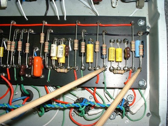
You may recall seeing this cap on "The Build - Part 4" page. It is referenced there as item # 5 in the photo of the "Layout of the phase inverter and NFB loop on the main board." Here's what it looks like now:
NFB circuit with presence cap removed
Another thing I'd noticed with the Normal channel was that the signal was too hot. For my tastes, it's nice to have this a little hotter than the Vibrato channel. Mikey dialed it back a bit for me by changing a some resistors connected to the first 12AX7 tube. If you are familiar with 12AX7 tubes, you will know it actually houses two triodes, so the 12AX7 is known as a dual triode tube.
There is a numbering scheme used for tube locations. Typically, the first input tube is known as V1. I assume the V stands for valve, which is the British word for a tube. Each triode in a 12AX7 has a name and they are V1A and V1B.
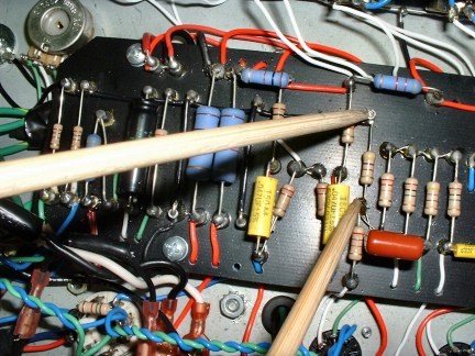
The first change Mikey made was to change the plate resistor in V1B from a 100k ohm metal film to a 1W/100k ohm carbon film resistor. Of note, V1A already had this type of resistor. Here's a photo with chopsticks pointing to the turrets for the identical V1 plate resistors.
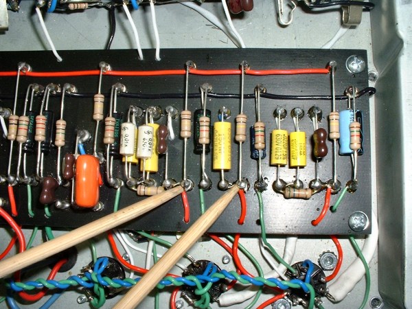
Plate resistors for V1A and V1B
Mikey also changed the cathode resistors for V1A and V1B from 820 ohms to 1W/1.5K ohms. Here's a photo with chopsticks pointing to the turrets for the identical V1 cathode resistors.
Cathode resistors for V1A and V1B
With the Mercury Magnetics Power Transformer installation and these tweaks, my amp was complete! We fired it up and it sounded like the best Deluxe Reverb you've ever heard. You know how you have an instant reaction to something that either appeals or doesn't appeal to you? Well, when I strummed the first chord it was love at first listen. There was another level of quiet authority about the amp, which is likely due to the new power transformer.
I took a couple of additional photos with the final tweaks and the installation of the power transformer. Here's how the outside of the chassis looks in its final state. Check out the size of the new, black power transformer. It's huge!
Completed chassis with all the Mercury Magnetics iron in place
And here are a couple of final shots of the interior of the chassis from left to right:
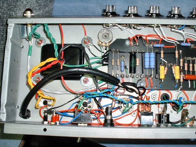
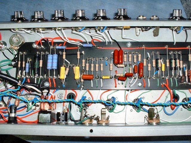
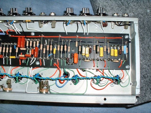
It had been another fun afternoon with Mikey and I would've enjoyed staying longer but he had a dinner appointment so I packed up my guitar and amp, petted Tucker (the friendly cat) and started the drive back to Lancaster County. This has been a wonderful project and as I write this in the middle of November, I must say the amp sounds better now than ever.